Insert Rod Object
 Click to attach a Grounding Rod
to a grounding grid connector on an existing grid. These are usually placed at
determined intervals along the grid as well as at any intersection point.
Click to attach a Grounding Rod
to a grounding grid connector on an existing grid. These are usually placed at
determined intervals along the grid as well as at any intersection point.

Note: Note that workflow
recommends the connector first being placed before the grounding rod is
attached.
By default, a Substation Filter is applied to the database to
only display the grounding rods as shown in the dialog below. The filter is as
follows:
Part_Type = GGRod
Select the Part Number and click the Place Symbol button for placement. Position the symbol by pointing the cursor at the desired location and pressing the left mouse button. The symbol is then placed in the diagram. The insertion point of the symbol will snap to the nearest grid point.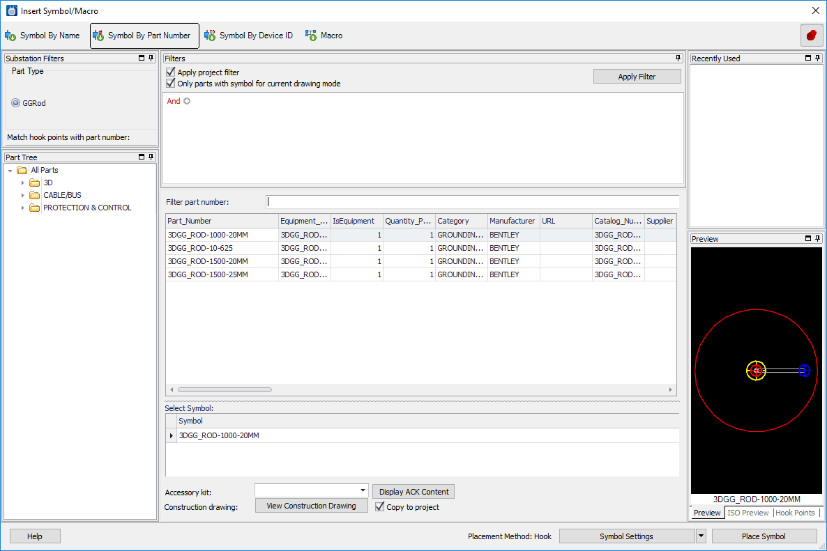
Once the symbol is placed, the Device Properties dialog will appear, allowing a device ID, part number and other items to be assigned.
| Setting | Description |
|---|---|
| Substation Filters Panel | By default, a Substation Filter is applied to the
database to only display the grounding grid connectors as shown in the dialog
below. The filter is as follows:
Part_Type <> GGRod |
| Filters Panel |
|
| Part Tree | The part tree hierarchy is defined in the Options > System Options > Part Tree dialog. You have the ability of organizing the tree by any of the fields in your parts database. You can filter the list of parts by selecting a folder in the tree. For example, if the tree lists all the manufacturers you can select a manufacturer in the tree and only parts from that manufacturer will be listed. |
| Filter part number | If you know the part number you wish to select you can simply type it in this text box. The list of parts will be filtered as you type; limiting the number of choices to pick from and thus narrowing in on the desired part number. |
| Part List | By default, this is filtered to list only the
Connector Objects in the parts database using the filter described above. You
can apply additional filters by selecting a field heading and picking the down
arrow which displays all the values for that field. Picking a value will filter
the list of parts and only list those that have that value.
Clicking on a field heading will sort the list in ascending order. Clicking a second time will sort it in descending order. You can click and drag the fields in any order you wish. Right clicking on any field heading will allow you select which fields from the parts database you wish to display. You can toggle on/off fields as desired.You can select (highlight) the part number that you want to place from the list. |
| Select Symbol List | The Symbol list displays the symbol for the current drawing mode that is called out by the selected part number record. If you have comma separated multiple symbols each one will be listed and you will be required to select the one you want to place. |
| Accessory Kit | If the selected part has an associated Accessory Kit, the name of the kit is displayed in this field. |
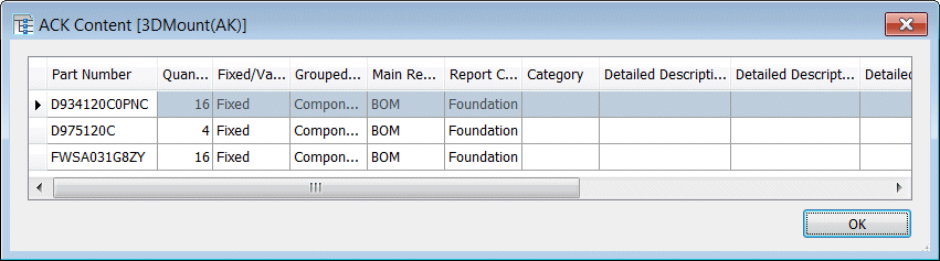
| Display ACK Content | Displays the content of the accessory kit selected in the Accessory Kit drop-down. |
| Copy to project | Enable this option to copy construction drawings selected in the View Drawings dialog to the current project. |
| View Constr. Drw. | If the selected part has an associated construction drawing(s), pressing this button displays the View Drawings dialog. |
| Recently Used Panel | Lists the last 10 part numbers that you had previously placed. The list is remembered the next time you restart the software and is not project specific. |
| Preview Panel | Shows a preview of the symbol for the selected part number based on the current drawing mode. |
| Hook Points Panel | This panel is only available when the current drawing mode is set to 3D Layout and it displays all the hook points in the symbol for the selected part number. |
| Placement Method | This identifies the current placement method setting. This value is set in the Substation Object Settings dialog. |
| Symbol Settings | Select the down arrow on this button to display a
flyout menu with 3 choices:
|
| Place Symbol | Places a new device, based on the symbol settings specified. If the current drawing mode is 3D Layout then the Substation Object Settings dialog will be displayed where additional settings can be specified before placing the device. |